
Four ways to build a wall.
Rammed-earth tires, insulated concrete forms, 3D-printed concrete and earth. We choose the structure building by building, for the site, the budget, the schedule and the code, and every one follows the same rule: mass inside, insulation outboard of it.
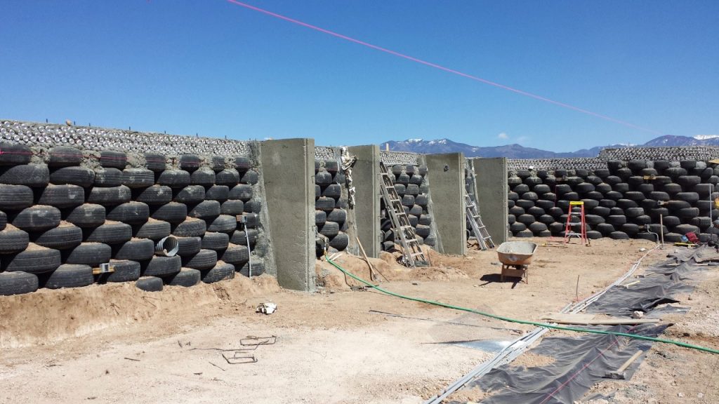
One rule, four walls.
Thermal mass on the inside to store the sun’s heat, insulation outboard of it to hold that heat in. How we get there depends on the building.
Rammed-earth tires
Upcycled tires packed with earth, bermed on the north. Enormous mass, plastered in earth.
Tire wallsInsulated concrete forms
Foam forms filled with reinforced concrete: a continuous insulated shell around a mass core.
Custom designs3D-printed walls
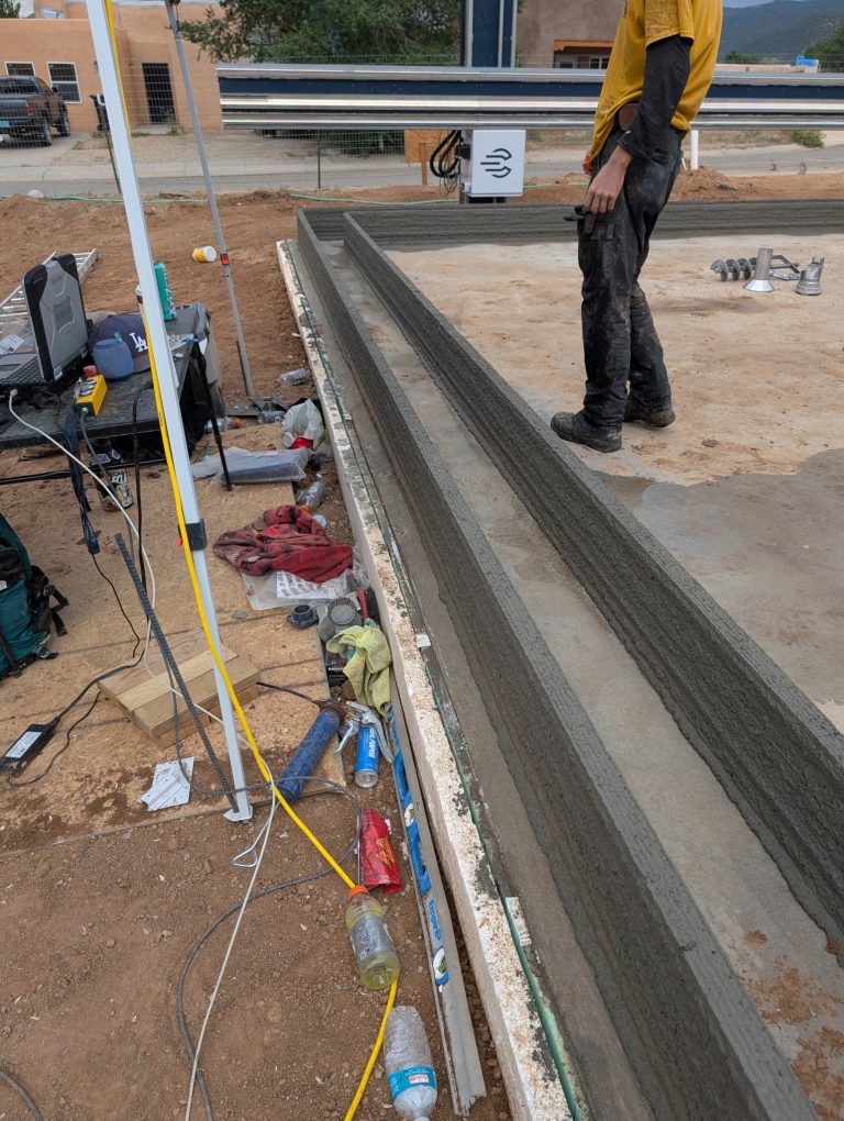
Two printed faces tied by a printed web, the cavity insulated. Printed on site from the drawings.
3D printingAdobe & earth block
Northern New Mexico's oldest way to build, laid in earthen mortar and finished in lime or mud.
ConstructionThe wall systems.
- W-1
Rammed-earth tires
Recycled tires packed with site earth: massive, load-bearing, ideal for earth-bermed Biotecture. Engineering below.
Tire walls - W-2
Insulated concrete forms
Foam blocks stacked like bricks, reinforced and poured solid: continuous insulation from R-20 to R-50 and up.
C-400 - W-3
3D-printed concrete
Dual walls printed from the digital model in days, with an insulated cavity and a mass inner skin.
C-300 - W-4
Earth: adobe + rammed earth
Local earth for mass walls, interior thermal-mass walls and restoration of historic adobe.
R-500
Side by side.
| W-1 Tire | W-2 ICF | W-3 3D print | W-4 Earth | |
|---|---|---|---|---|
| Structure | Load-bearing rammed-earth tires | Reinforced concrete core | Printed dual wall | Adobe block or rammed earth |
| Thermal mass | Very high, exposed inside | In the core, behind the inner foam | Inner printed skin | High, exposed inside |
| Insulation | Earth berm and exterior insulation | EPS foam both faces, R-20 to R-50+ | Insulated cavity between skins | Added outboard of the wall |
| Materials | Recycled tires, site earth | EPS foam, rebar, concrete | Printable concrete; testing geopolymer and earth mixes | Local earth, straw, sand |
| Best for | Earth-bermed Biotecture | Conventional plans, multi-story, below grade, high wind or wildfire | Repeatable, affordable housing; curved forms | Interior mass walls, the Southwest, historic restoration |
Rammed earth in steel-belted rubber.
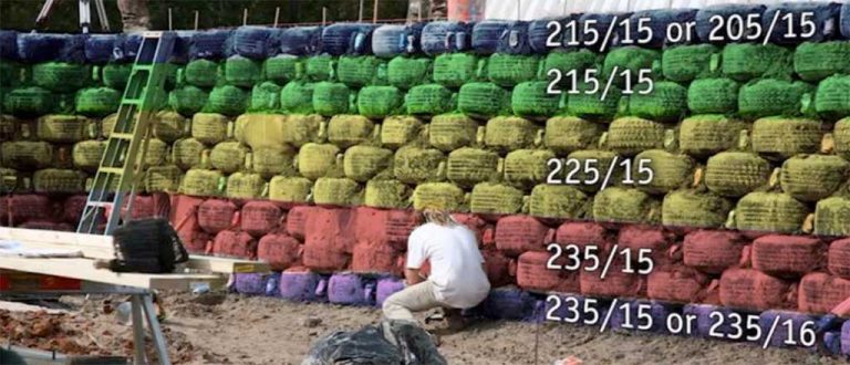
Recycled automobile tires, packed solid with earth by sledgehammer and laid in a running bond like adobe or block. A sand, straw and adobe mix packs the gaps and plasters the face. The result is a massive, load-bearing wall that stores the day’s heat and gives it back at night.
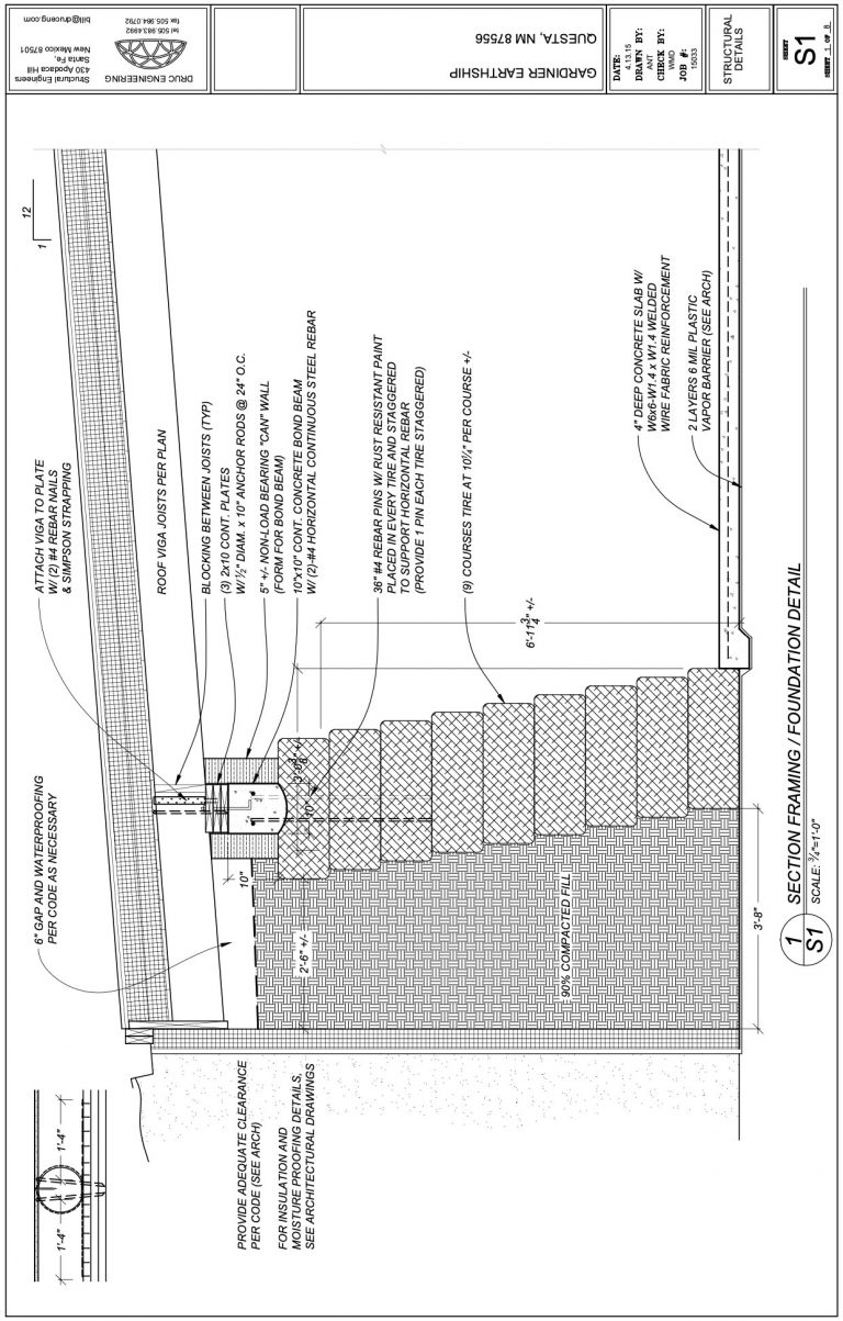
A typical wall is about 2′-4″ wide, the diameter of a tire, and 7 to 10 feet high to give the roof slope for drainage. Total weight at the bottom, at floor level, is about 3,600 pounds at most, so the pressure on the soil is only about 1,550 pounds per square foot.
That is low enough that a concrete footing, which would itself put 2,700 psf on the soil at a 16-inch width, isn’t needed to spread the load. On dry, competent, undisturbed native soil that is kept dry, the concrete foundation can be omitted.
“When the house is built on dry competent natural soil, and is kept dry, it is my opinion that the concrete foundation may be omitted.”
Kenneth D. DeLapp, P.E., Structural Engineer
Tire walls: field-tested, 1990.
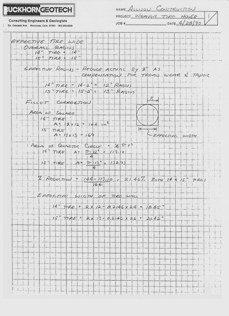
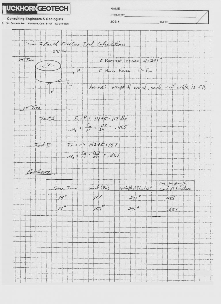
Buckhorn Geotech tested earth-filled tire walls on site at the Dennis Weaver residence near Ridgway, Colorado, using the actual materials and methods of construction.
| Tire-to-tire friction | Coefficient 0.728 to 0.877, with no mortar between tires (worst case). |
|---|---|
| Tire-to-earth friction | Coefficient 0.485 to 0.651, governed by the soil beneath rather than the tire. |
| Filled tire weight | 241 lb for a 14-inch tire; 378 lb for a 15-inch tire. |
| Free-standing wall | Resists an equivalent fluid pressure of about 36 pcf. No lateral load until the wall is restrained. |
| Braced wall | With U-shaped or battered ends, wall returns and a finished roof diaphragm, resists lateral earth pressures up to 128 pcf. |
| Adobe plaster | Over 2,000 psf cohesion dry but about 150 psf saturated, so it is given no structural value. |
“The rammed earth-filled tire walls… will provide safe and dependable support for the structure. The laterally braced walls have sufficient strength from their massive structure and internal tire-to-tire friction to resist the sliding and overturning pressures imparted to the walls from the outside.”
Thomas E. Griepentrog, P.E., Buckhorn Geotech · April 30, 1990
Tire walls: what the engineering asks for.
- 01Drainage
Controlled surface and subsurface drainage keeps the foundation dry for the life of the building. No standing water within 50 feet; landscape grading steers runoff around the building; check for underground springs.
- 02Soil
Have a soils engineer confirm bearing capacity against local snow loads. Bottom tires sit on dry, firm, undisturbed soil with no organic debris or soft pockets.
- 03Battered north wall
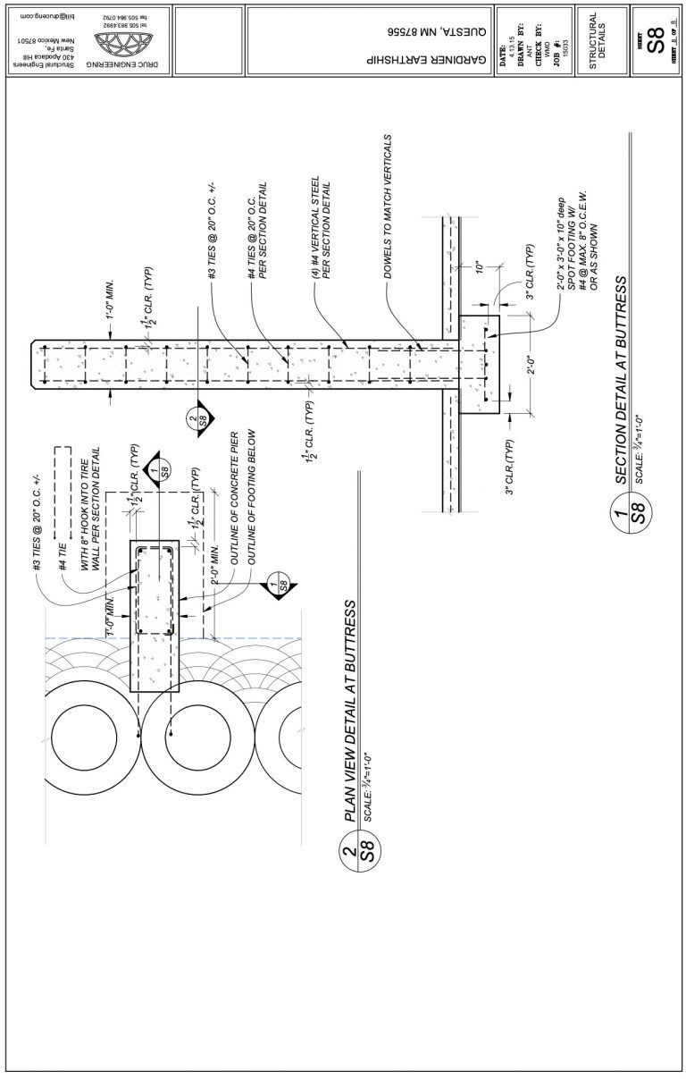
Straightening and battering the back wall keeps its strength when the top is braced by the roof. Above 6 feet, backfill with compacted granular fill placed as the wall rises, and interlock every course at the corners.
- 04Frost
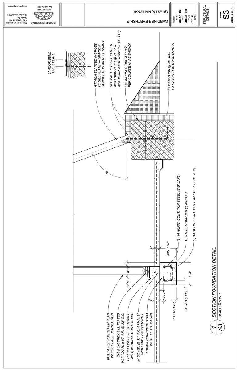
Protect the bottom courses under the front glazing wall and atop earth cliffs by berming or burial to the depth your building official requires.
- 05Roof attachment
A concrete bond beam cast into the top course, with anchor bolts at least 7 inches into the concrete and 3 inches of cover, ties the roof to the wall and braces it.
- 06Lateral loads
Site-specific soil pressures set the load the roof diaphragm must carry; above set limits, the plywood diaphragm needs blocking or added bracing.
Details + calculations.
Get the tire wall report.
The full engineering support file, with the DeLapp letters and the Buckhorn Geotech evaluation, for your building department.
From the knowledge base.
Start with the site.
Tell us where it is and what you want the building to do. We design and build across the country and around the world.